
The coordinates
How a pixel knows where it is, and how to use that position to draw gradients, stripes and circles.
In the previous chapter every pixel had the same color. Now you are going to achieve something much more interesting: each pixel getting its own.
For that, the shader needs an answer to one question: where is this pixel? That answer is the Uv, and you have been seeing it since the first shader without us stopping to look at it closely. Today we do.
Step 1: the Uv turned into color#
Copy Template.cs as Coordinates.cs and change the class name to Coordinates. Then replace the line in Fragment with this one:
return Make.Vec4(pixel.Uv.X, 0f, 0f, 1f);Here we are using the pixel's position as if it were the amount of red. Run the work cycle:
But first, tell the viewer about the new shader. In Viewer/Program.cs, add this line to the switch, above the _ => line:
"Coordinates" => new Coordinates().ToMGFX(gl),Now run it:
dotnet yotsuba add MyShaders/MyShaders.csproj --target spirv --target monogame && dotnet run --project Viewer -- Coordinates
Black on the left and red on the right. What you are seeing is the value of Uv.X drawn as brightness: at the left edge it is 0 (no red) and at the right edge it is 1 (full red).
This is the best tool for understanding a shader: turning a number into color so you can see it. You will use it many times.
Step 2: the other coordinate#
Now change the line to show Uv.Y in the green channel:
return Make.Vec4(0f, pixel.Uv.Y, 0f, 1f);
Look closely: green grows downward. At the top Uv.Y is 0 and at the bottom it is 1.
This surprises almost everyone, because in math and in function plots the Y axis grows upward. But screens are numbered from the top-left corner, the way text is read: left to right and top to bottom. That is how we defined it in the viewer's rectangle, and in many engines it is the same.
Now put both coordinates together, one in each channel:
return Make.Vec4(pixel.Uv.X, pixel.Uv.Y, 0f, 1f);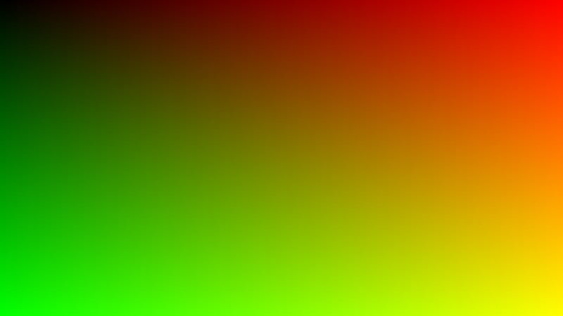
This image is a coordinate map. Each corner tells you its position:
| Corner | Uv | Color you get |
|---|---|---|
| Top left | (0, 0) | Black |
| Top right | (1, 0) | Red |
| Bottom left | (0, 1) | Green |
| Bottom right | (1, 1) | Yellow |
If you ever doubt what is happening with the positions in a shader, paint Uv.X and Uv.Y as colors and you will know at once.
Step 3: repeating the pattern#
So far Uv.X goes from 0 to 1 only once. What if we want the gradient to repeat several times? Multiply first:
float x = (pixel.Uv.X * 4f) % 1f;
return Make.Vec4(x, 0f, 0f, 1f);
There are two new things in that line:
pixel.Uv.X * 4fmakes the number go from0to4instead of0to1.% 1fis the remainder of the division by 1. That is, it keeps only the decimal part:0.3gives0.3, but1.3gives0.3and3.7gives0.7.
Together, they make the number rise from 0 to 1, go back to 0, rise again, and so on four times.
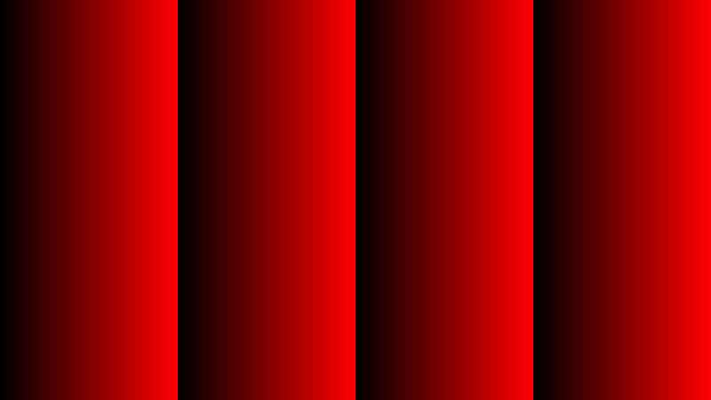
Change the 4f to 10f and you will see ten stripes. Change the 1f of the remainder to 0.5f and see how the stripes change. Playing with these numbers is the best way to make them stick.
Step 4: putting the origin in the center#
The Uv starts at the top-left corner. But to draw a circle in the middle, or anything centered, we need the point (0, 0) to be at the center of the screen. For that we subtract 0.5:
float dx = pixel.Uv.X - 0.5f;
float dy = pixel.Uv.Y - 0.5f;
return Make.Vec4(dx, dy, 0f, 1f);
dx and dy are "how far I am from the center" in each direction. They no longer go from 0 to 1, but from -0.5 to 0.5.

Look at the result carefully. The left half has no red and the top half has no green. Why? Because there dx and dy are less than zero, and as you saw in the colors chapter, the GPU clips negatives to 0. In other words: what you see is the color half-cut at the center. The center itself, where dx and dy are 0, is the darkest point.
Step 5: the distance to the center#
With dx and dy we can tell how far each pixel is from the center. The calculation is dx * dx + dy * dy: each number multiplied by itself, and the two results added. At the center it gives 0, and the further away you go, the bigger it gets.
Careful: that result is not the exact distance. It is the distance multiplied by itself (in math it is called "the squared distance"). To tell who is further away it works just as well, and it saves us a harder calculation. Let us use it to paint a spot of light:
float dx = pixel.Uv.X - 0.5f;
float dy = pixel.Uv.Y - 0.5f;
float light = 1f - (dx * dx + dy * dy) * 4f;
return Make.Vec4(light, light, light, 1f);
Let us read the third line from the inside out:
dx * dx + dy * dyis the number from before:0at the center and bigger and bigger toward the outside.* 4fmakes it grow faster, so the effect reaches the edges.1f - ...flips it: now it is1at the center (white) and falls toward the edges (black).
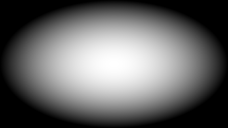
It works, but something is wrong. We asked for a round spot, and an oval came out. What happened?
The oval problem#
The Uv always goes from 0 to 1, both horizontally and vertically, no matter the shape of the window. Our window is 800 by 450 pixels: it is wider than tall. So 0.1 of width is 80 pixels, but 0.1 of height is only 45. The distances we compute are not equal in both directions, and the circle stretches.
This is one of the problems beginners ask about most: "why is my circle oval?" The solution is to correct that difference. If the window is 1.78 times wider than tall, we have to multiply dx by 1.78 so that it "measures the same" as dy.
But for that the shader has to know the width and height of the window, and it cannot guess that from inside. The program that draws it knows, and it has to pass it along.
Step 6: data handed over by the program#
A piece of data that the program passes to the shader is called a uniform. It is called that because it is uniform: it has the same value for all the pixels of the image. The width of the window is a good example, because it does not change from one pixel to another.
Declaring one takes three steps. Do them in order.
First, create a file MyShaders/Context.cs that describes the data package:
namespace MyShaders;

public struct Context
{
    public float Width;
    public float Height;
}
It is a struct with two numbers. Later we will add a third.
Second, in Coordinates.cs, add this line at the very top with the other using lines:
using YotsubaShader.GlslSyntax.Resources;using YotsubaShader.HlslSyntax.Resources;using YotsubaShader.MslSyntax.Resources;using YotsubaShader.WgslSyntax.Resources;using YotsubaShader.SpirvSyntax.Resources;Third, inside the Coordinates class, right before Vertex, declare the data:
    [uniform, layout(0, 0)]
public Context Data; [cbuffer, register("b0")]
public Context Data; [constant, buffer(0)]
public Context Data; [uniform, @group(0), @binding(0)]
public Context Data; [Uniform, DescriptorSet(0), Binding(0)]
public Context Data;This line has three parts:
[uniform]tells the compiler: "this is not an ordinary variable, it is data that reaches me from outside".[layout(0, 0)]is its address inside the GPU. For now write it exactly like this; when you have more than one piece of data, each one will get a different address.public Context Data;is the data itself. It is calledDataand its type is the struct we just created.
And now, inside Fragment, you can use it like any other value: Data.Width and Data.Height.
Step 7: fixing the circle#
Now use the width and height to correct dx. Replace the contents of Fragment with this:
float aspect = Data.Width / Data.Height;
float dx = (pixel.Uv.X - 0.5f) * aspect;
float dy = pixel.Uv.Y - 0.5f;
float light = 1f - (dx * dx + dy * dy) * 4f;
return Make.Vec4(light, light, light, 1f);The new line is the first one: aspect is the width divided by the height, that is, how many times wider than tall the window is. With 800 and 450 it is 1.78. In the second line we apply it to dx.
Run the work cycle.
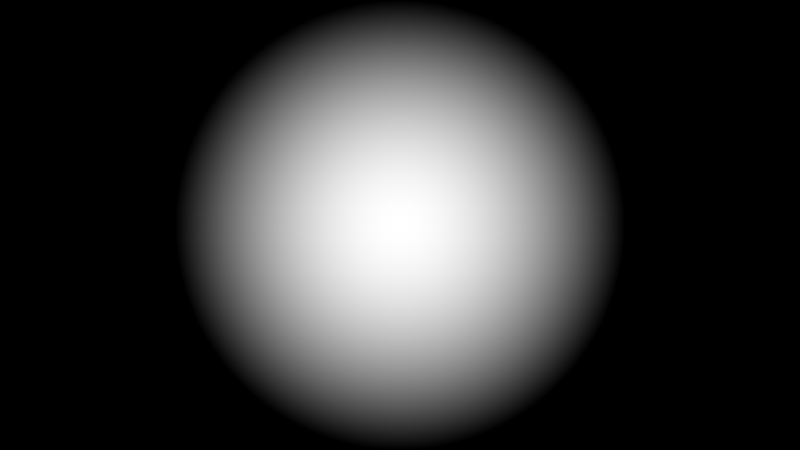
Now it is a circle. Try one more thing: stretch the window with the mouse (or change the 800 and the 450 in Viewer/Program.cs). The circle stays round, because the shader recomputes the aspect with every new size.
All together#
This is the complete file, in case you want to compare it with yours:
using YotsubaShader.GlslSyntax;
using YotsubaShader.GlslSyntax.Resources;
using YotsubaShader.GlslSyntax.Types;
using YotsubaShader.Language;
namespace MyShaders;
public class Coordinates
{
[uniform, layout(0, 0)]
public Context Data;
[ShaderStage(Stage.Vertex)]
public Pixel Vertex(Corner corner)
{
Pixel pixel;
pixel.Position = Make.Vec4(corner.Position.X, corner.Position.Y, 0f, 1f);
pixel.Uv = corner.Uv;
return pixel;
}
[ShaderStage(Stage.Fragment)]
[return: location(0)]
public vec4 Fragment(PixelIn pixel)
{
float aspect = Data.Width / Data.Height;
float dx = (pixel.Uv.X - 0.5f) * aspect;
float dy = pixel.Uv.Y - 0.5f;
float light = 1f - (dx * dx + dy * dy) * 4f;
return Make.Vec4(light, light, light, 1f);
}
}using YotsubaShader.HlslSyntax;
using YotsubaShader.HlslSyntax.Resources;
using YotsubaShader.GlslSyntax.Types;
using YotsubaShader.Language;
namespace MyShaders;
public class Coordinates
{
    [cbuffer, register("b0")]
    public Context Data;
[ShaderStage(Stage.Vertex)]
public Pixel Vertex(Corner corner)
{
Pixel pixel;
pixel.Position = Make.Vec4(corner.Position.X, corner.Position.Y, 0f, 1f);
pixel.Uv = corner.Uv;
return pixel;
}
[ShaderStage(Stage.Fragment)]
[return: SV_Target]
public vec4 Fragment(PixelIn pixel)
{
float aspect = Data.Width / Data.Height;
float dx = (pixel.Uv.X - 0.5f) * aspect;
float dy = pixel.Uv.Y - 0.5f;
float light = 1f - (dx * dx + dy * dy) * 4f;
return Make.Vec4(light, light, light, 1f);
}
}using YotsubaShader.MslSyntax;
using YotsubaShader.MslSyntax.Resources;
using YotsubaShader.GlslSyntax.Types;
using YotsubaShader.Language;
namespace MyShaders;
public class Coordinates
{
    [constant, buffer(0)]
    public Context Data;
[ShaderStage(Stage.Vertex)]
public Pixel Vertex(Corner corner)
{
Pixel pixel;
pixel.Position = Make.Vec4(corner.Position.X, corner.Position.Y, 0f, 1f);
pixel.Uv = corner.Uv;
return pixel;
}
[ShaderStage(Stage.Fragment)]
[return: color(0)]
public vec4 Fragment(PixelIn pixel)
{
float aspect = Data.Width / Data.Height;
float dx = (pixel.Uv.X - 0.5f) * aspect;
float dy = pixel.Uv.Y - 0.5f;
float light = 1f - (dx * dx + dy * dy) * 4f;
return Make.Vec4(light, light, light, 1f);
}
}using YotsubaShader.WgslSyntax;
using YotsubaShader.WgslSyntax.Resources;
using YotsubaShader.GlslSyntax.Types;
using YotsubaShader.Language;
namespace MyShaders;
public class Coordinates
{
    [uniform, @group(0), @binding(0)]
    public Context Data;
[ShaderStage(Stage.Vertex)]
public Pixel Vertex(Corner corner)
{
Pixel pixel;
pixel.Position = Make.Vec4(corner.Position.X, corner.Position.Y, 0f, 1f);
pixel.Uv = corner.Uv;
return pixel;
}
[ShaderStage(Stage.Fragment)]
[return: location(0)]
public vec4 Fragment(PixelIn pixel)
{
float aspect = Data.Width / Data.Height;
float dx = (pixel.Uv.X - 0.5f) * aspect;
float dy = pixel.Uv.Y - 0.5f;
float light = 1f - (dx * dx + dy * dy) * 4f;
return Make.Vec4(light, light, light, 1f);
}
}using YotsubaShader.SpirvSyntax;
using YotsubaShader.SpirvSyntax.Resources;
using YotsubaShader.GlslSyntax.Types;
using YotsubaShader.Language;
namespace MyShaders;
public class Coordinates
{
    [Uniform, DescriptorSet(0), Binding(0)]
    public Context Data;
[ShaderStage(Stage.Vertex)]
public Pixel Vertex(Corner corner)
{
Pixel pixel;
pixel.Position = Make.Vec4(corner.Position.X, corner.Position.Y, 0f, 1f);
pixel.Uv = corner.Uv;
return pixel;
}
[ShaderStage(Stage.Fragment)]
[return: Location(0)]
public vec4 Fragment(PixelIn pixel)
{
float aspect = Data.Width / Data.Height;
float dx = (pixel.Uv.X - 0.5f) * aspect;
float dy = pixel.Uv.Y - 0.5f;
float light = 1f - (dx * dx + dy * dy) * 4f;
return Make.Vec4(light, light, light, 1f);
}
}What you learned#
pixel.Uvis the pixel's position:Xfrom0to1to the right,Yfrom0to1downward.- To see a number, paint it as a color. It is the fastest way to understand what a shader does.
%repeats a pattern. Subtracting0.5moves the origin to the center.- To tell how far a pixel is from the center, use
dx * dx + dy * dy. - An oval circle is fixed by taking into account that the window is wider than tall, and for that the shader needs a uniform: a piece of data handed over by the program.
Next: Deciding with if.